This product specification sheet is applicable to BACKBONE Steel Frame and is only a preliminary specification. The detailed content and range of application will only take effect after communicating and confirming with the customer.
- BACKBONE Steel Frame has a similar appearance to the aluminum frame and can be adapted to various module production lines without changing the installation method.
- BACKBONE Steel Frame, with indestructible characteristics, uses a double-beam structure.
- The A-side dragon design features anti ash accumulation and high power generation.
- The B-side Load-bearing beam has strong load resistance.
- The C-side stiffening beam can prevent deformation and stress release.And the C-side is narrow resulting in a high double-sided yield.


A-side
The top surface of the frame,which is parallel to the battery cell once the frame is assembled with the photovoltaic panel.
B-side
The lateral surface of the frame,which is perpendicular to the battery cell once the frame is assembled with the photovoltaic panel.
C-side
The bottom surface of the frame,which is parallel to the battery cell once the frame is assembled with the photovoltaic panel.
PRDUCT SPECIFICATION MODEL
| Frame model | slot (mm) | A-side width (mm) | B-side width (mm) | C-side width (mm) | Wall thickness (mm) | Coating weight (g/m²) | Linear density (g/m²) | Color |
|---|---|---|---|---|---|---|---|---|
BACKBONE Steel Frame B30 | 6.2 | 10 | 30.0 | 21 | 1.0 ± 0.11 | 275 | 601 | Black / Primary color |
BACKBONE Steel Frame B29 | 4.7 | 10 | 28.5 | 21 | 1.1 ± 0.13 | 275 | 655 | Black / Primary color |
Accessory | — | — | — | – | 1.5 ± 0.14 | 275 | 27 g/pcs | Black / Primary color |
Note one: The thickness of the steel is according to GB/T 25052-2010 Continuously hot-dip coated steel sheet and strip – Tolerances on dimensions, shape and weight.

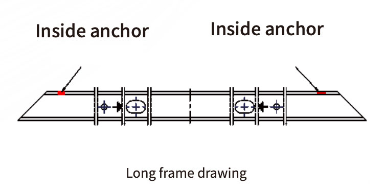
Note two:The frame size and installation holes are customized according to the customer’s drawings.
MATERIAL
The steel frame and accessory both are made of hot-dip galvanized aluminum magnesium steel strip.
| Type of steels | Mpa Yield strength | Chemical analysis (melting analysis)% (mass fraction) no more than | ||||||
|---|---|---|---|---|---|---|---|---|
| C | Si | Mn | P | S | Ti | Nb | ||
| S350GD+ZM275 | ≥350 | 0.2 | 0.6 | 1.7 | 0.1 | 0.045 | 0.1 | 0.1 |
| S450GD+ZM275 | ≥450 | 0.2 | 0.6 | 1.7 | 0.1 | 0.045 | 0.1 | 0.1 |
| S550GD+ZM275 | ≥550 | 0.2 | 0.6 | 1.7 | 0.1 | 0.045 | 0.1 | 0.1 |
(The substrate quality shall comply with YB/T 4761-2019 standard)
Hot dip galvanized aluminum magnesium alloy coating
| Chemical elements | Chemical composition (mass fraction) | |||
|---|---|---|---|---|
| Aluminum | Magnesium | Zinc | Other elements besides zinc | |
| Content | 1% – 13% | 1% – 6% | margin | < 1% |
TECHNICAL REQUIREMENTS FOR THE BACKBONE STEEL FRAME
| Projects | Unit | Inspection standard |
|---|---|---|
| Overall appearance | / | The frame has no zinc layer falling off and no zinc slag; blowing marks, cold bending indentations, and linear scratches are allowed. A, B, and C surfaces are inspected at a distance of 1m under 1000 Lux lighting conditions with direct vision (visual acuity 1.0), referenced to the sealed sample. No overall deformation; punching and other machining deformation < 0.5 mm. No dirt, metal chips, rust spots, or watermarks on the frame. |
| Chromatic aberration | / | Silver gray: The appearance color is consistent within the same batch and matches the sealed sample. The sealed sample is stored in a vacuum or nitrogen cabinet. No obvious color difference is observed at a distance of 1 meter between different batches. |
| Projects | Unit | Inspection standard |
|---|---|---|
| Scratches, Abrasion, Bumps | / | At a light intensity of 1000 Lux, inspection distance 60–80 cm, visual acuity ≥ 1.0: Side A: Black spots ≤2 mm² (≤1 point); burr ≤0.15 mm; scratch total length ≤10 mm, width ≤0.2 mm, ≤2 scratches; abrasion ≤10 mm² (≤2 areas); bumps ≤3 mm² (≤2 points); no substrate exposure; Side B: Black spots ≤2 mm² (≤2 points); burr ≤0.15 mm; scratches ≤50 mm, width ≤0.4 mm, ≤2 scratches; abrasion ≤15 mm² (≤3 areas); bumps ≤5 mm² (≤4 points); no substrate exposure; Side C: Black spots ≤2 mm² (≤3 points); burr ≤0.15 mm; scratches ≤50 mm, width ≤0.5 mm, ≤3 scratches; abrasion ≤15 mm² (≤3 areas); bumps ≤5 mm² (≤4 points); no substrate exposure. |
| Profile head | / | The processed parts are free of dirt, metal chips, and burrs, and do not cause secondary damage after assembly. |
| Longitudinal side camber of C side | mm | < 1‰ of total length |
| Longitudinal side camber of B side | mm | < 1‰ of total length |
| Plane clearance | mm | ≤ 0.3 mm |
| Torsion degree | mm | ≤ 0.5 mm/m |
| Coating thickness | g/m² | Coating thickness: Average ≥ 29 μm, minimum ≥ 24.5 μm (5 points tested, each ≥ 100 mm apart) |
| Projects | Unit | Inspection standard |
|---|---|---|
| Length | mm | Refer to the drawing |
| Drawing force of the accessory | / | The corner code pull force bears 20KG without falling off or deforming |
| Salt spray resistance | / | There is no red rust at the 4000h non-section and meets the grounding continuity requirements |
| 45° chamfer | / | ±0.5° |
| Module load resistance | Pa | The front 6000Pa / The back 3000Pa |